 By
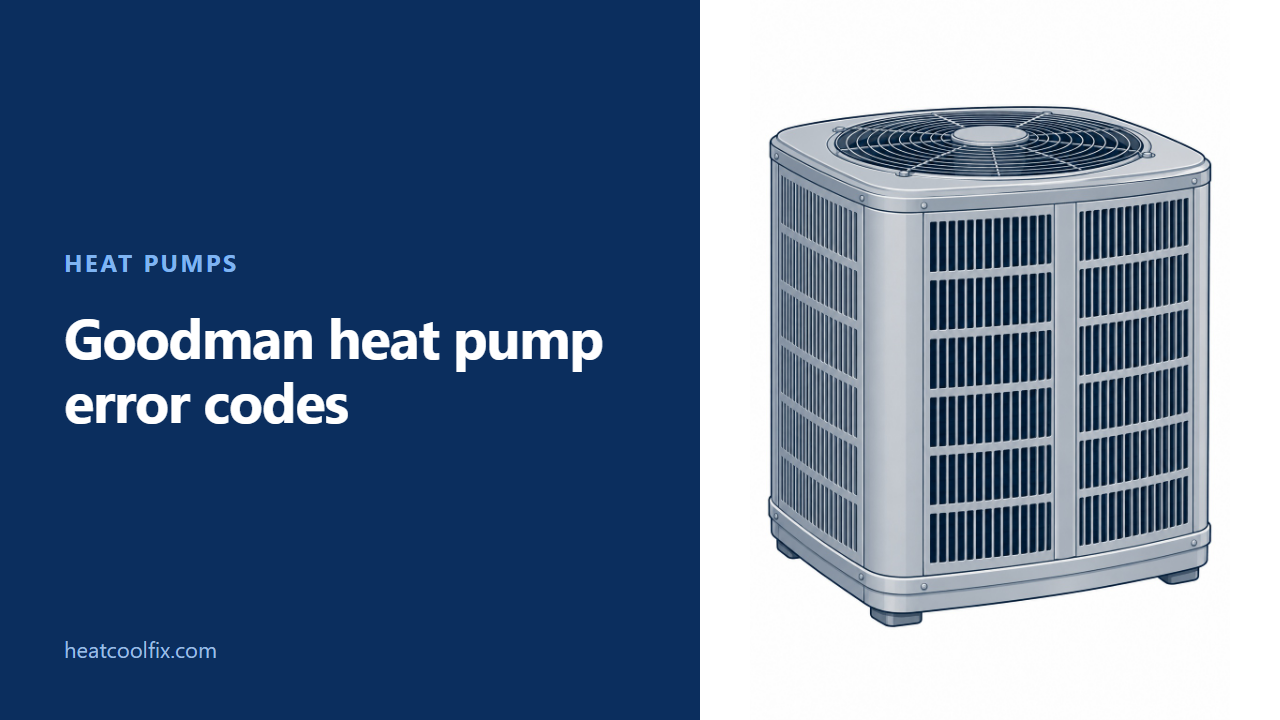
For Goodman GSZC16 and GSZC18 equipment with the matching PCBHR105 control, 01 identifies a low pressure trip or low side fault, while L1 is a low pressure lockout. Code 04 is locked rotor. Record the exact letters and numbers, and leave the outdoor service panel closed.
Goodman heat pump error codes need the control version as well as the outdoor model. In Goodman’s PCBHR105 chart, 01 can identify a low pressure trip or low side fault. L1 is the separate low pressure lockout. Keep the letter when you report it.
This guide covers the Goodman GSZC16 and GSZC18 families listed in service manual RS6200007r25, using its PCBHR105 diagnostic rows. The manual also contains other controls. Ask service to confirm the installed board before applying this table, especially after a previous control replacement.
If your message comes from the gas furnace, use the Goodman furnace code guide. The same brand on two cabinets does not make their diagnostic charts interchangeable.
Before you start
What to carry: a torch, the installation paperwork and a phone for recording the thermostat screen. Read an accessible outdoor model label without removing a panel. Include whether heating or cooling was selected.
Gas or electric? This page is for the named split heat pumps and their outdoor control. Record any separate indoor furnace message separately. Do not apply a furnace flash count to this board’s display.
Renting? Give maintenance the outdoor model and complete message. An existing service report can identify the board without asking you to reach it.
Goodman’s manual reserves service for trained personnel and warns that multiple power sources may be present. It requires all power disconnected before servicing. Leave the outdoor cabinet closed; opening it to read a board, test a capacitor or measure voltage is not an owner check.
Use a message already available at the thermostat or in a technician’s report. If you have no code, describe the symptom instead. Do not bypass a pressure switch or replace a fuse to keep trying a stopped unit.
01 and 02 are different from L1 and L2
Preserve the letter and the operating condition
Goodman’s PCBHR105 table gives 01 two descriptions: low side fault and low pressure cutout trip. Its 02 rows likewise distinguish a high side fault from a high pressure cutout trip. The technician uses the accompanying symptoms and operating history to identify the condition.
| Board code | Goodman’s PCBHR105 description | What to report |
|---|---|---|
| 01 | Low side fault or low pressure cutout trip | The full message and selected mode |
| L1 | Low pressure cutout lockout after three trips within the same thermostat demand | The L, the number and whether the unit stopped |
| 02 | High side fault or high pressure cutout trip | Any fan or run-time observation already made safely |
| L2 | High pressure cutout lockout, labelled three trips | The original code before anyone resets it |
Goodman’s low pressure rows list low refrigerant charge, a restricted liquid line and an indoor blower failure among possible causes. The high pressure rows list a blocked condenser coil and an outdoor fan that is not running. Those are diagnostic possibilities, not instructions to add refrigerant or order a fan motor.
Leave pressure, refrigerant and electrical checks to the technician. Give them the heating or cooling mode along with the code so they investigate the condition that actually occurred.
03 and 04 need different investigations
Do not turn code 04 into a compressor diagnosis
Goodman’s PCBHR105 chart calls 03 short cycling. Its row describes the last four runs each lasting less than three minutes, with the compressor protector not tripped and both pressure switches closed. Possible causes include intermittent thermostat demand and a faulty compressor relay.
The same chart calls 04 locked rotor. It describes four consecutive compressor protector trips with average run time between trips below 15 seconds. Listed possibilities include seized compressor bearings, a failed run capacitor, faulty capacitor wiring and low line voltage.
A technician checks those possibilities before selecting a part. The chart includes a 24-volt control power cycle for clearing 04, but that service instruction does not diagnose the cause. Repeated resetting is not the next owner step for a returning fault. Our heat pump reset guide explains why the equipment’s own instructions matter.
b0 and b9 point toward indoor airflow
Report whether air is reaching the rooms
In Goodman’s PCBHR105 table, b0 means the circulator blower is not running when it should. Its possible causes include an indoor blower problem and a communication error between the indoor and outdoor equipment.
Goodman describes b9 as airflow lower than demanded. Its possibilities include a blower problem, blocked filters, restrictive or undersized ductwork and mismatched indoor and outdoor units. A dirty filter is one possibility in that list, not the definition of b9.
Note an accessible filter’s condition and whether furniture covers a room opening. Follow the indoor unit’s own owner instructions for any filter care. Do not reach into a blower compartment or change installer airflow settings. If the accessible path is clear, pass that finding to service rather than assuming the board is faulty.
Sensor and fuse messages stay with the technician
Keep A2, A3 and E5 with the exact spelling
Goodman’s PCBHR105 chart defines A2 as an outdoor air temperature sensor fault and A3 as an outdoor coil temperature sensor fault. Their listed possibilities include a shorted, open, disconnected or out-of-range sensor. A3’s row also describes failure to operate in heating mode.
Goodman defines E5 as an open fuse and lists a short in low voltage wiring as the possible cause. Its corrective action starts with finding and correcting that short. Leave fuse replacement and circuit checks to service instead of treating the fuse alone as the repair.
Send the complete code, model, mode and any previous repair details. That gives service useful evidence while the cabinet stays closed.
What each one takes
| Task | Work involved |
|---|---|
| Match the model and control | Paperwork and the service record |
| Record an available message | A thermostat photo and the selected mode |
| Investigate 01, 02, L1 or L2 | Professional pressure, airflow and electrical checks |
| Investigate 04 | Compressor, capacitor, wiring and supply diagnosis |
| Investigate b0, b9, A2, A3 or E5 | Control-specific blower, sensor or circuit work |
Questions people ask
Where is the Goodman heat pump error codes PDF?
The source is the manufacturer-authored Goodman service manual RS6200007r25, April 2021. GSZC16 and GSZC18 appear on page 11. The PCBHR105 diagnostic tables start on page 78.
Does this cover every Goodman heat pump?
No. This guide names the GSZC16 and GSZC18 families and PCBHR105 table. Another series, board or indoor air handler needs its own matching chart.
Is 01 the same as L1?
No. In this Goodman table, 01 identifies a low side fault or low pressure trip. L1 identifies a low pressure lockout after repeated trips. Preserve the letter.
Does code 04 mean I need a new compressor?
Goodman’s possible causes also include a capacitor, its wiring and low line voltage. The chart calls for diagnosis before a part is chosen.
Can I remove the panel just to photograph the display?
Leave that to service. Goodman’s safety instructions reserve service for trained personnel and require isolation of all power sources before servicing.
The other heat pump guides: a heat pump with no heat, an outdoor unit that will not run and Amana’s separately scoped heat pump codes.
Sources: Goodman Service and Troubleshooting RS6200007r25, April 2021, safety pages 1 and 2, Goodman model identification page 11, PCBHR104/105 summary page 70 and PCBHR105 detailed diagnostic tables pages 78 to 82. Manufacturer-authored manual saved from InspectAPedia.